PAVAS Firmware Update
This explains how the program firmware in the PAVAS module can be updated.
Why change the firmware?
The first point of concern is that mistakes can be made when updating the firmware. These procedures have been design to minimize those risks but they still remains. The PAVAS software will change from time to time. This changes may be caused by the discovery of errors or bugs. The deployment of new features can also be accomplished with a firmware upgrade. There are two ways to change the firmware. The first is to return the Micro Controller Unit( MCU) to the factory. The second way is to update the firmware in the field. This can be done quickly which would immediately make the PAVAS unit serviceable. All the PAVAS parameters are stored in Flash PROM which is not located on the MCU board. All the data log files are store on an SD card, so upgrading the MCU firmware will not impact either the parameters or the data log files.
Mechanics of firmware changes
The firmware is updated by transmitting a Binary file (.bin) to the PAVAS. This file is transferred over the USB link. The other part of the process is to have a program that can read the files, place the PAVAS unit in a mode to upload the new firmware and then to transfer the firmware. The Binary files can be sent via email so distribution is fast and effective. The main effort involved is setting up the software tools to program or “flash” the MCU. Fortunately, this only has to be done once.
The Firmware Flash Tool
There are several flash tools available and the one chosen here is by Espressif. Here is a link to the free download . The download consist of a zip file which is expanded so the the executable file, flash_download_tools_v3.6.8.exe. The file only runs under Windows. When the file is run, it takes a short time to be responsive. During this time a DOS or Console command screen is displayed. Allow the initialization program to complete running.
The Start Screens
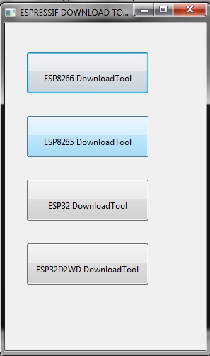
Two screens are displayed at start up. The first screen shows the two modes of Developer and Factory. On this screen, select Developer. The second screen show the device types. Select ESP32 DownloadTool.

The Flash Command Screen
The third screen shows the flash commands and configuration. This is where the works starts.
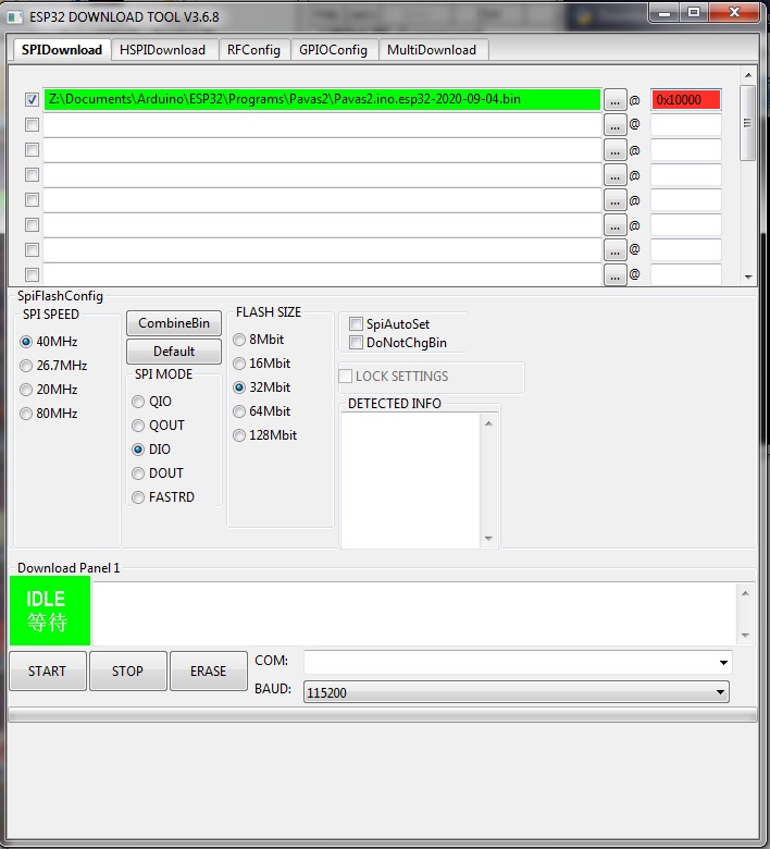
The first task is to browse to the Binary file. This is done by selecting the first button labeled (…). This will open a file explorer and allows a file to be selected. The check box to the left should be selected. This selection means that file will be used in the flash process. The last item at the top of the screen is to set the address in memory where the Binary file will be loaded to. This address must be 0x10000 as shown in the picture. The 0x indicates it is a hexadecimal address. Using a different or incorrect address will not allow the new program to run and could destroy other existing programs making the PAVAS unit totally unresponsive. The options are the SPI speed which is set to 40 MHz, the SPI mode which is DIO and Flash Size which is set to 32 Mbit.
The Communications Port
The PAVAS unit should be connected to the computer via a USB connection. The actual port that communicates from the Computer to the PAVAS unit will vary from machine to machine and is the same port that PavasTerm finds when connected. It can also be found by looking at the ports in the Device Manager. It will have a name starting with Silicon labs since that is the manufacturer of the USB driver
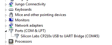
The port number will appear in the COM drop down list in the Flash program and should be selected.
The Flashing Process.
The flashing process is only supported by a Windows program. Describing the Flashing process is complicated and a problem may occur related to the Windows driver. To show the whole flashing process, a video has been generated. The link is provided here.
USB Sync problem with Windows
The Flash program attempts to set the PAVAS unit to the download or Flash mode. This is performed by manipulating two control lines call DTR and RTS. The timing of procedure is critical and sometimes it fails on Windows machines. The workaround is to press the Boot button on the MCU board while the Flash tool is trying to set the PAVAS unit to the flash mode. A picture of the MCU board is shown below with the location of the Boot button.
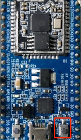
Pressing the button can be difficult when the MCU board is attached to the stack of other boards. An insulated probe can be used to press it or it can be removed from the stack and pressed more easily. The button contact must occur while the Flash program is trying to sync. The Sync process is repeated several times before failing. The Sync icon will change to Downloading once synchronization has been achieved. The Bluetooth and Ethernet addresses will be displayed and the progress bar will start to move.
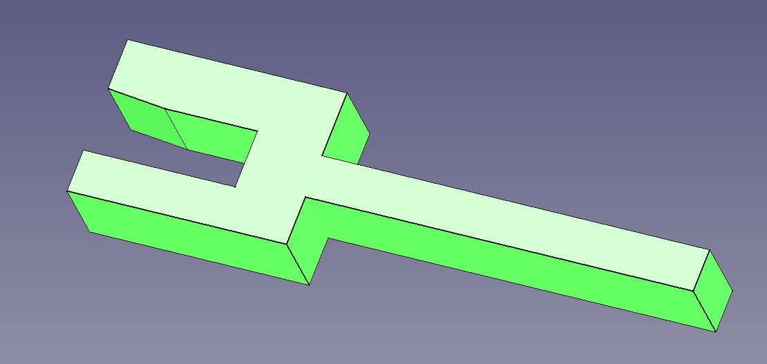
The Boot Fork
This is a specialized tool that has been developed to allow the Boot button to be held down while the printed circuit boards are still in the stack. The thicker tyne of the Boot Fork should be placed on the Boot button and the fork slid towards the board. The Boot switch closure, though faint, can often be heard. The Sync process can proceed with the fork in place. A picture of the Boot Fork is shown below. Due to board manufacturing anomalies, the switch may not close. In this case, slight down pressure on the Boot Fork stem can be applied to close the switch. Unfortunately, a further problem is that the USB extension cable used in the PAVAS unit has a right angle connector which is used to connect to the microprocessor board. This interferes with access to the boot button. The solution is to remove the extension cable and connect to the computer with another USB cable with a straight connector.
Verify Boot Mode
The PavasTerm program provides a simple way to verify that the MCU will enter the Boot mode. The procedure is to apply the Boot Fork and then select Reset MCU from the Communications menu. If the MCU enters boot mode it will respond with
rst:0x1 (POWERON_RESET),boot:0x3 (DOWNLOAD_BOOT(UART0/UART1/SDIO_REI_REO_V2)) waiting for download.
To quit this mode, remove the Boot Fork and select Communications/ Reset MCU again.
